A key consideration when designing or updating an electrical system with large capacity motors is the sizing of the associated system and choice of components. Operational flexibility and redundancy needs often dictate multiple smaller units which allows for efficient operation at partial loads and reduces peak starting current. Capital cost factors favor fewer larger drives, but its starting characteristics can create high stress on the system at start-up. Soft start technologies (RVSS) and variable speed drives (VFD) help to reduce the impacts on your electrical system at start up, however, limits set by the utilities and system design can often be breached. Powerside has solutions that can significantly improve the startup behaviors of your large drives, bringing overall inrush conditions to a lower level and reducing transformer overload transients with reduced thermal overloads.
A real application example is given below with supporting graphs to show how Powerside solutions can significantly improve system operations:
System description
The primary Motor driven Compressors M1 and M2 are two 4.16kV, 2000HP units started sequentially via soft starters to rated speed before being sequentially loaded to 100%. Prior to M1 and M2 start, a 4.16kV, 2000HP Variable Frequency Drive as well as some additional Low Voltage loads are brought online. The 4.16kV bus feeds M1 and M2, while the 2000HP VFD is fed from TX-A; a 34.5kV:4.16kV transformer rated 8MVA.
Main objective
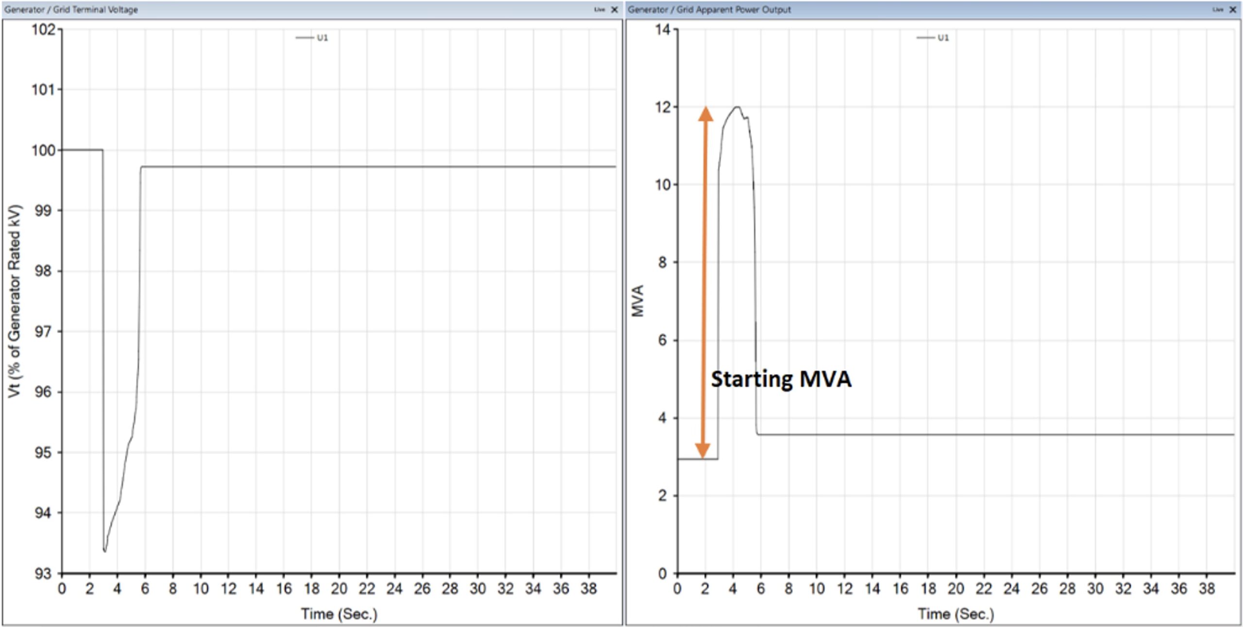
Starting (inrush) MVA should be limited to 4MVA at utility side. This should be considered during starting M1 and M2.
Project objectives and imposed limits
Transformer TX-A is 8000/8960 KVA and any transformer overload should be prevented.
Voltage on 4.16kV should remain in acceptable levels to prevent MV VFD unexpected shut-down
Motor thermal overload curves should be considered during acceleration.
Scenarios to be considered
M1 starts direct online (without soft starter)
M1 starts with soft starter
M1 starts with soft starter + 4MVAR capacitor bank
M1 is fully loaded and M2 starts with soft starter + 4MVAR capacitor bank
Inrush MVA, voltage drops at 4.16kV & utility (34.5kV) and motor starting graphs are shown for each scenario.
Scenarios
Please note simulation starts at T:3s for better visibility.
A) M1: starting in direct online mode at T-3s, M2: OFF
UTILITY MVA & VoltageM14.16kV BusTX-A
B) M1: starting with soft starter (Voltage Control 40%-70%) at T:3s, M2: OFF
UTILITY MVA & VoltageM14.16kV BusTX-A
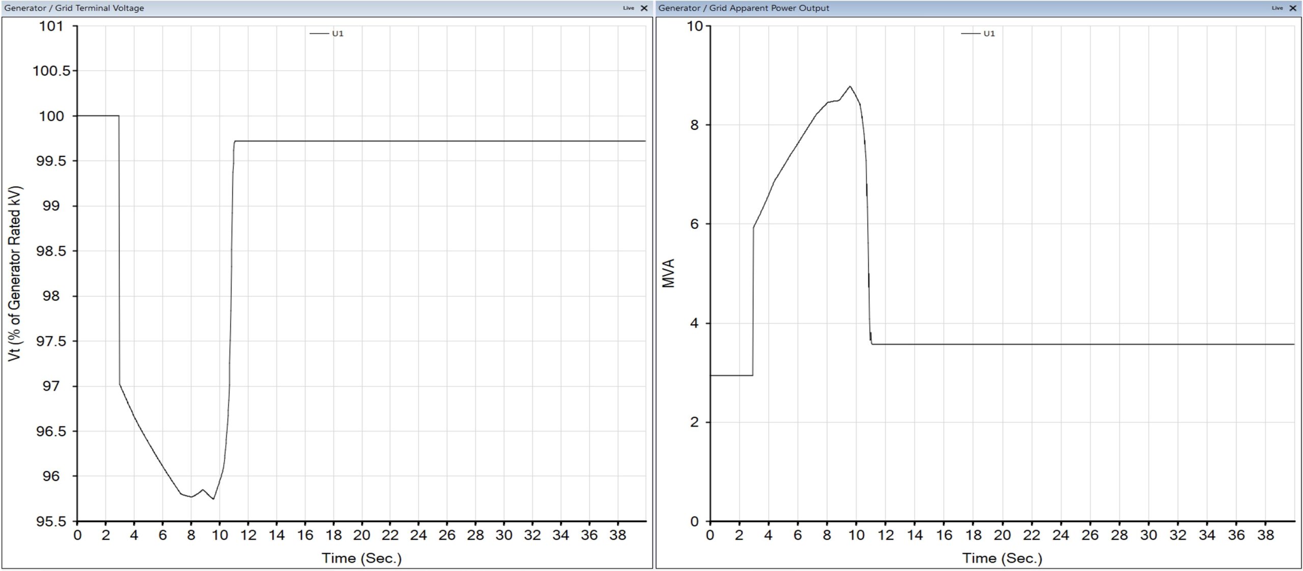
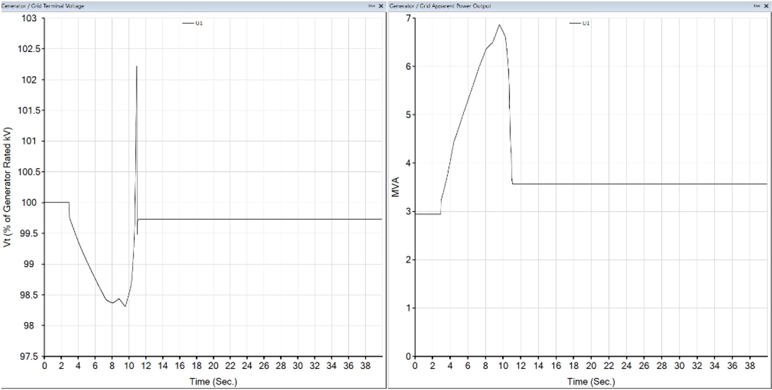
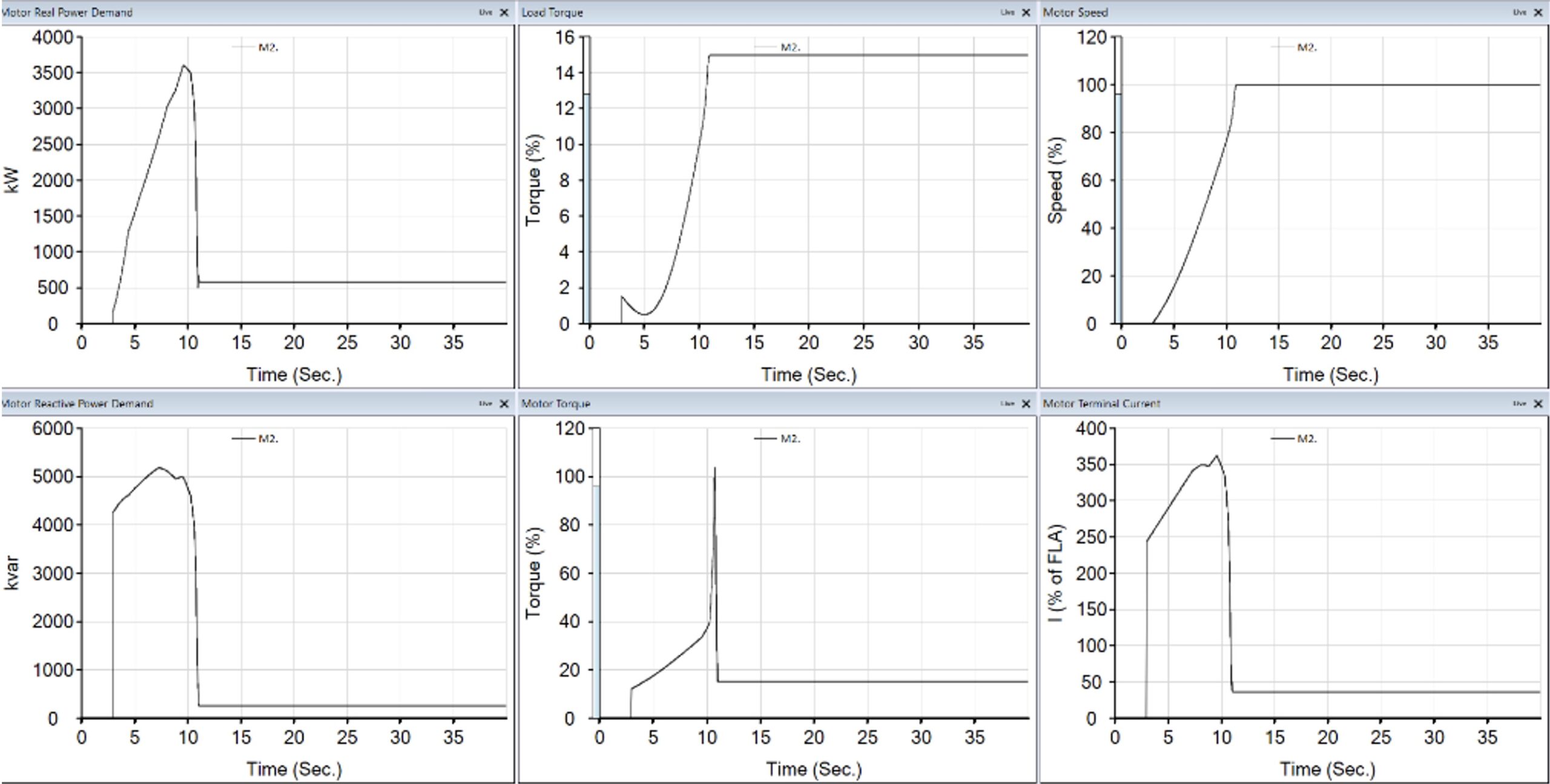
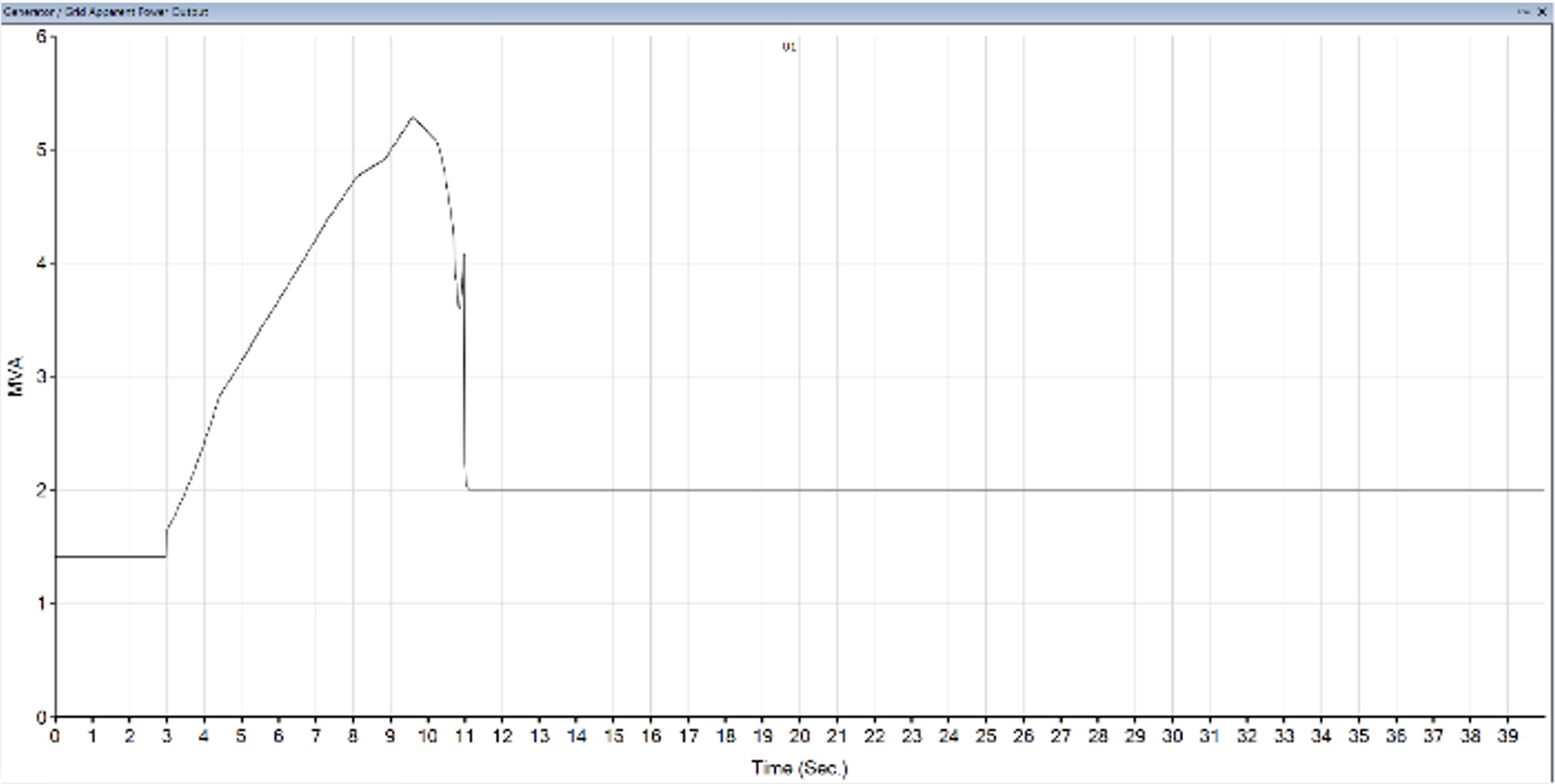
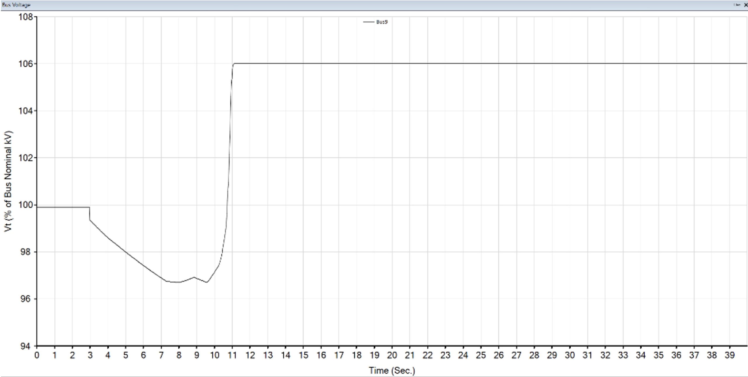
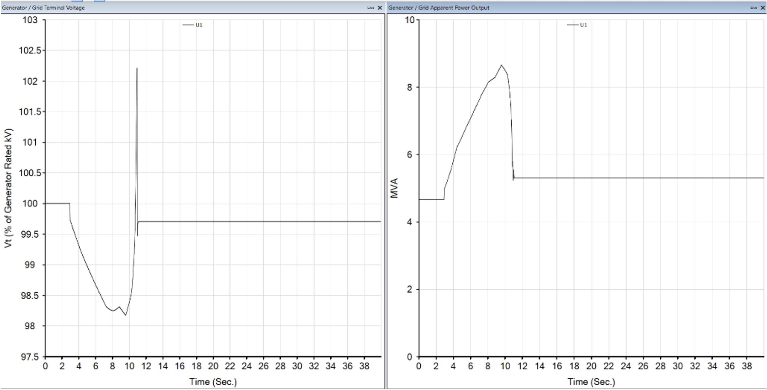
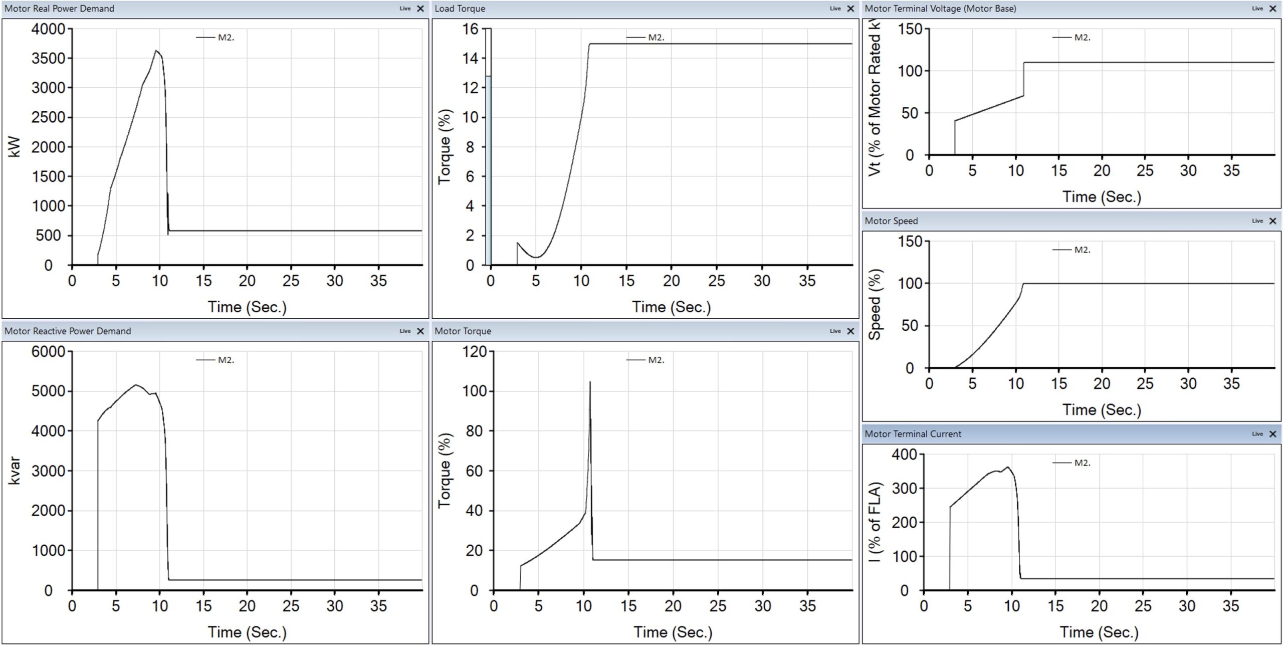
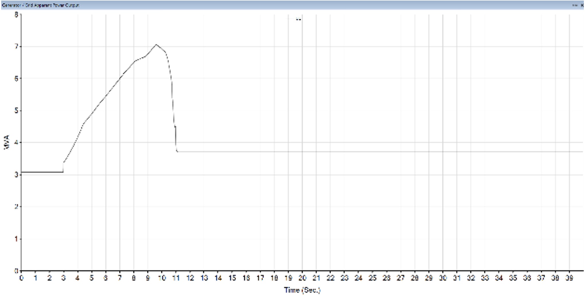
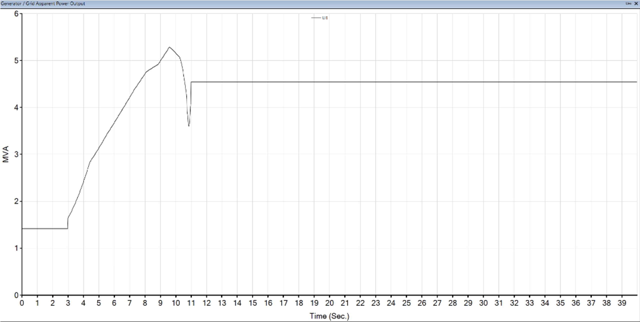
C) M1: starting with soft starter (Voltage Control 40%-70%), M2: OFF+ 4MVAR (will be OFF after motor reached the rated Speed)
UTILITY MVA & VoltageM14.16kV BusTX-A
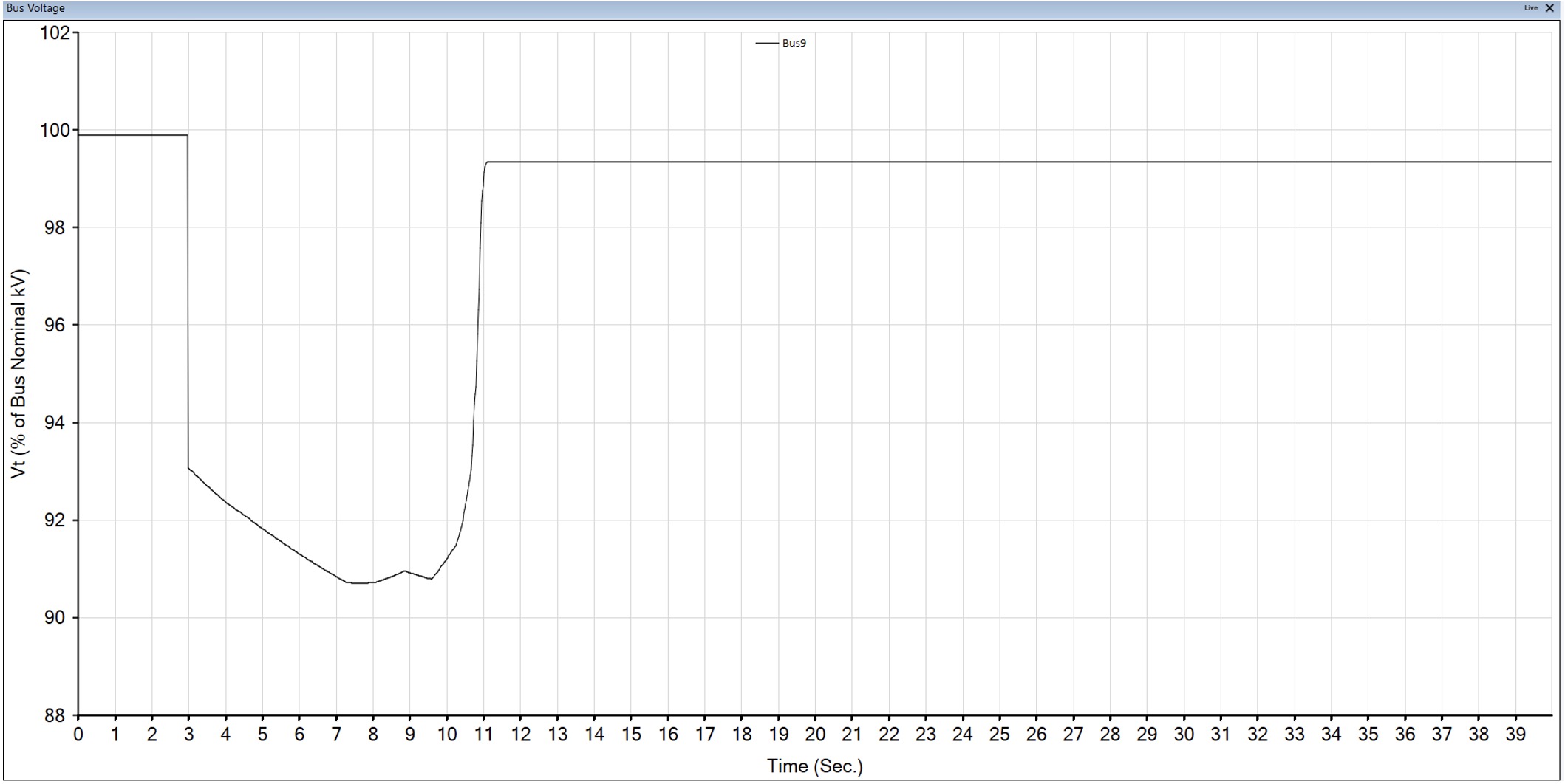
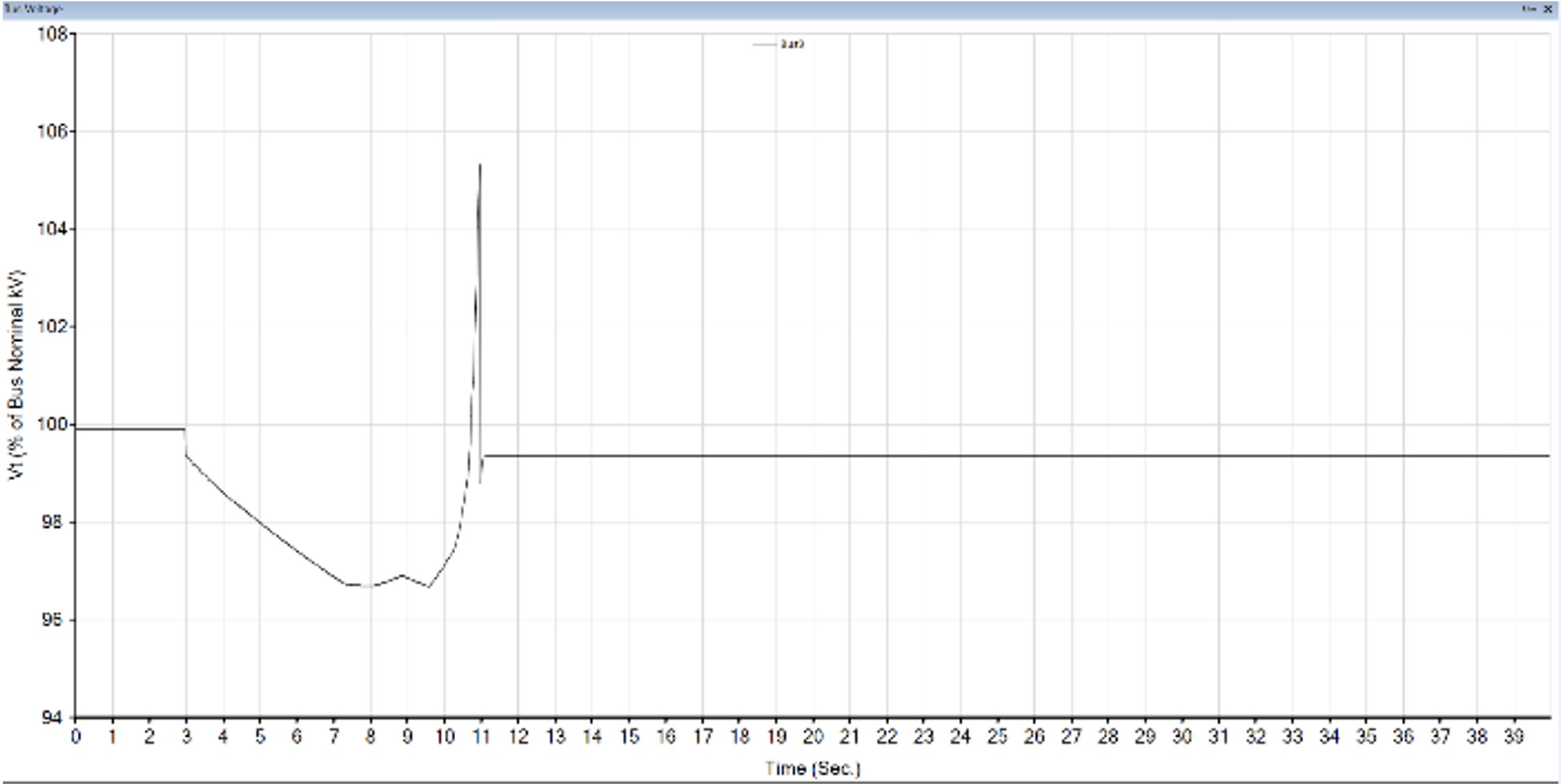
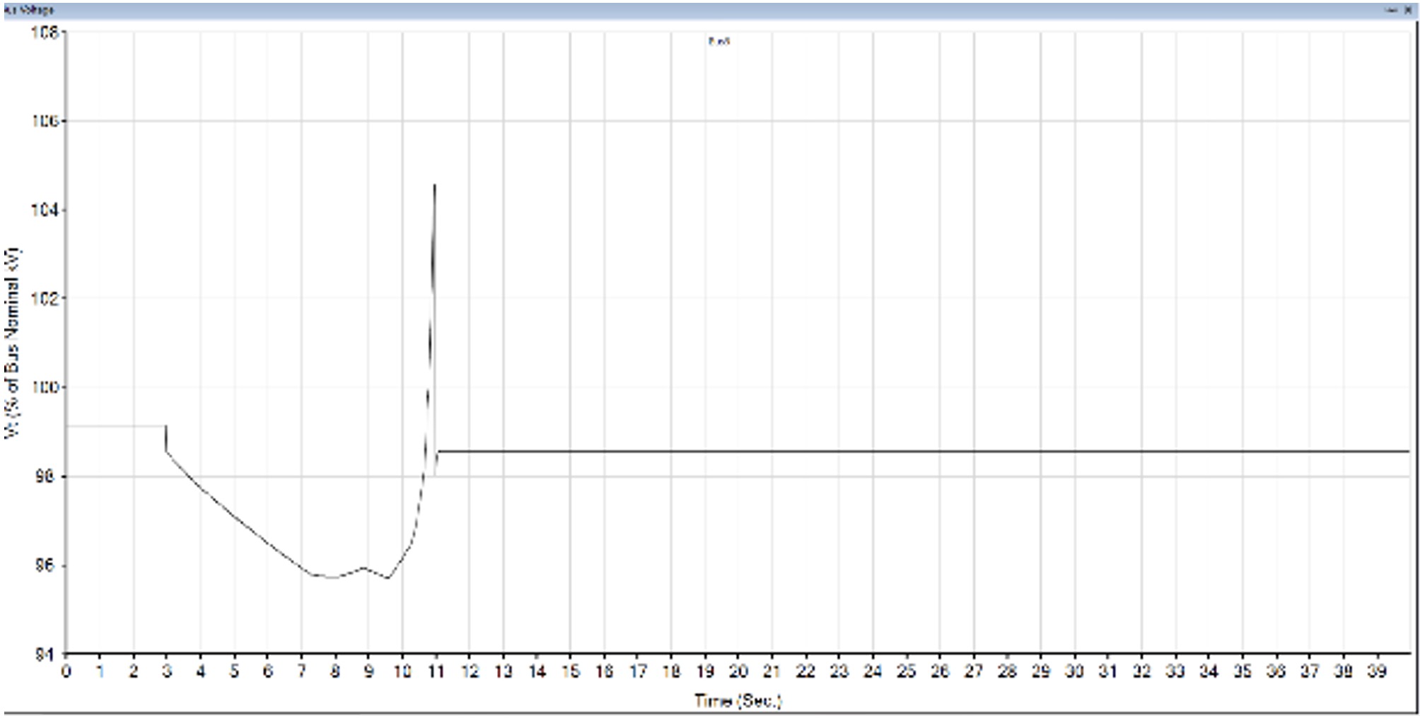
* Result if we don’t switch off the capacitors after motor reaching the rated speed (Scenario C):
4.16kV Bus
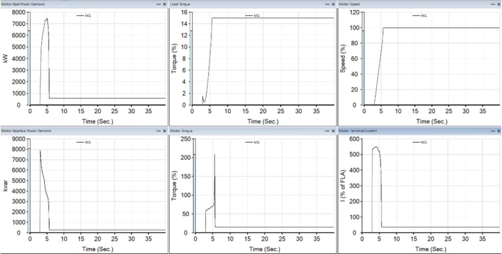
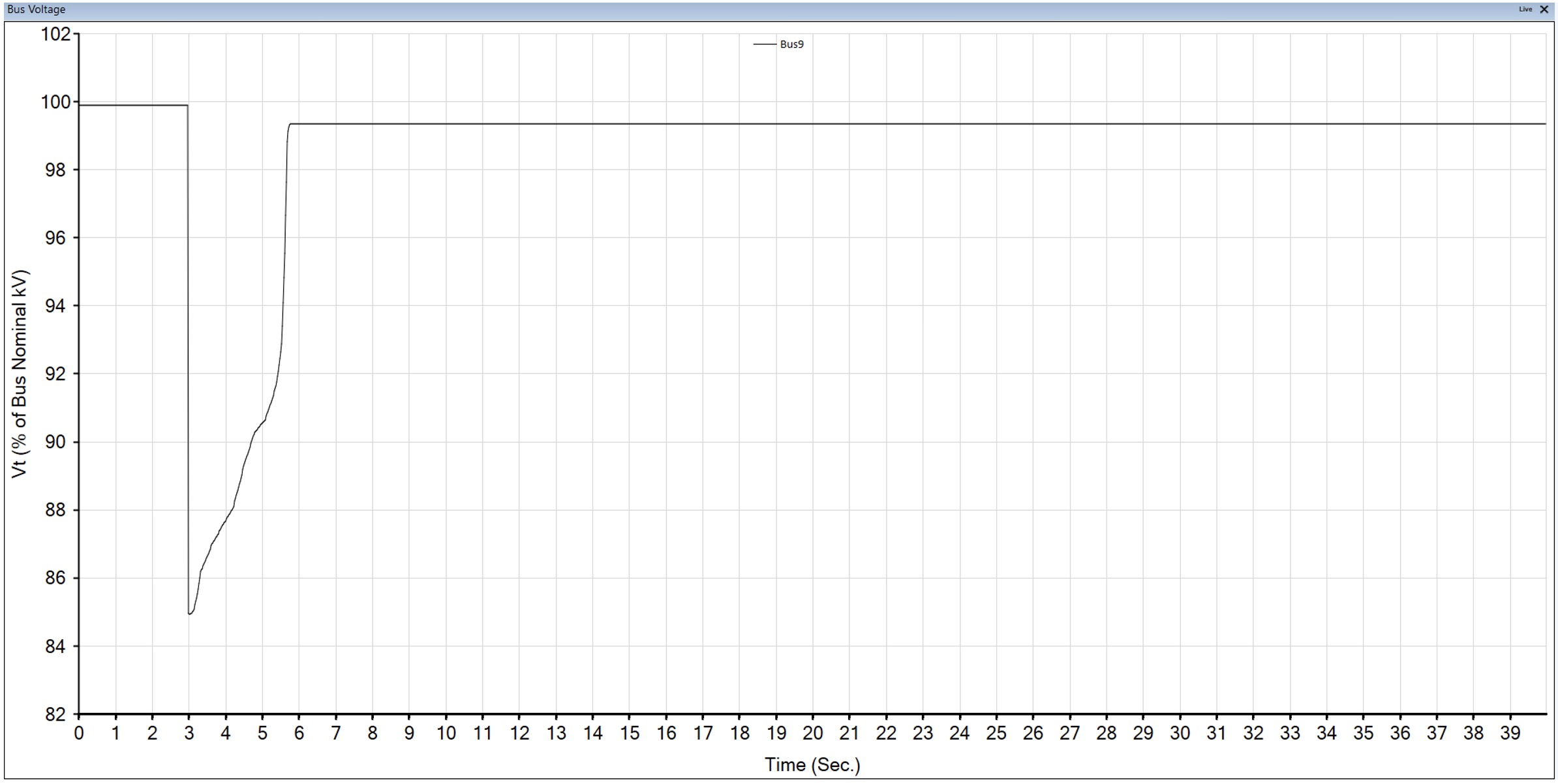
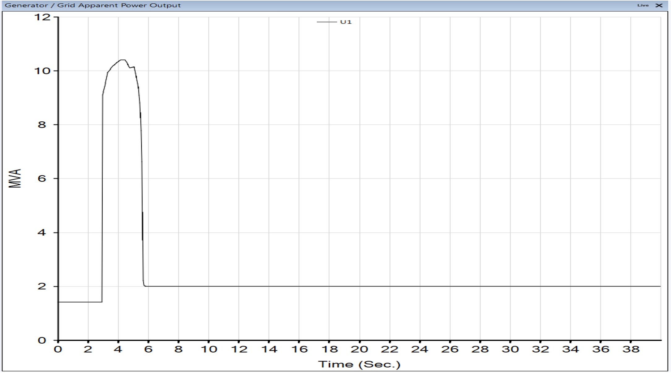
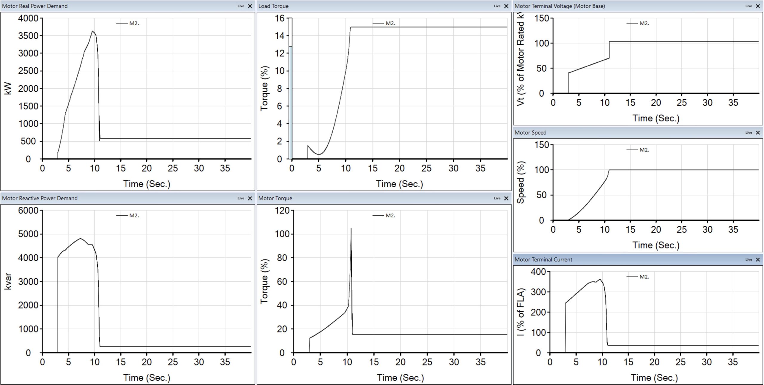
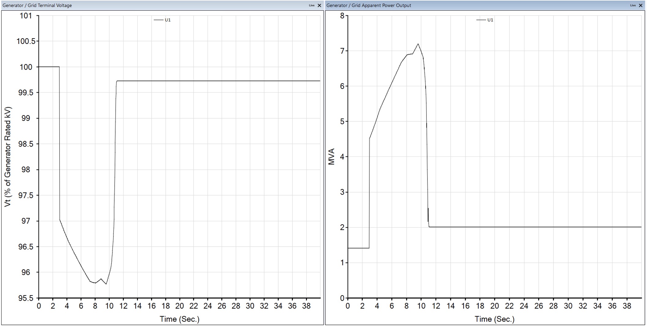
D) M1: ON (full loaded) M2: starting with soft starter (Voltage Control 40%-70%) + 4MVAR (will be OFF after motor reached the rated Speed)
UTILITY MVA & VoltageM24.16kV BusTX-A
* Result if we don’t switch off the capacitors after motor reaching the rated speed (Scenario D):
TX-A
Results and Conclusions
Using a soft starter can reduce the apparent power overshoot from 9MVA for starting M1 in direct online mode to less than 6MVA, but it is still higher than the required 4MVA limit set by the Utility.
Adding a 4MVAR Capacitor bank to the system will limit the starting MVA to 4MVA as per utility requirement and maintain the voltage between 95%-105% on 4.16kV bus to prevent MV VFD malfunction but this is not the only requirement. The soft starter should provide an acceptable voltage ramp during M1 and M2 acceleration (40%-70% voltage ramp with current limit of 430%). The 4MVA requirement can therefore only be achieved when both kW and KVAR are controlled. The Capacitor bank primarily reduces required KVAR from the utility, but the soft starter should mainly control the kW (in order to reduce the motor acceleration torque).
40%-70% voltage ramp is therefore achieved by voltage control on soft starter as shown from the study. Any control mode like current control should provide the same voltage on the motor bus during acceleration which is also acceptable. Even reducing the voltage to lower values is acceptable but must be sufficient to start these large motors.
The soft starter manufacturer should confirm that adding a Capacitor bank on the soft starter bus will not affect the soft starter functionality.
The capacitor bank study led to the proposed 2*2MVAR configuration. Prior to starting the first compressor (M1), a signal from soft starter will be sent to bank to energize it and after a short delay. M1 will start unloaded. The bank will be de-energized at this point and need at least 5 minutes to be recharged and prepared for M2 start up. M1 will then be fully loaded, and a same procedure will be followed to start M2 in unloaded condition.