Skip to the content
by Seth Johnson, Vice-President, Large Projects and Medium Voltage
Starting large motors connected directly on-line represents a significant power challenge due to the large inrush currents produced during start up. Traditionally, Variable Frequency Drives and Reduced Voltage Soft Starters have been used to ramp up the motor speed progressively. A VFD or RVSS controls the motors speed and torque by varying the frequency or voltage. This limits the inrush power demand from the network and, consequently, the voltage sag. Such solutions however are expensive and can have undesired drawbacks in certain applications.
One cost effective alternative to VFDs and RVSSs is to use a capacitor bank. Until recently, this approach was seldom used due to the high current and voltage transients caused by frequent capacitor switching. However, new technologies such as Point-On-Wave and Zero-Voltage Switching technologies now allow for a smooth connection which avoids these current and voltage transients resulting in a prolonged component life cycle. This article describes the cost and technical advantages of using SynchroMVar MV capacitor bank with Point-On-Wave switching technology for large motor loads requiring frequent start and stop operations. Comparisons with VFDs and RVSSs in several applications are discussed, from an individual motor application up to trains of motors turned on in succession for pumping stations and gas compression plants.
Problems associated with large DOL motor start
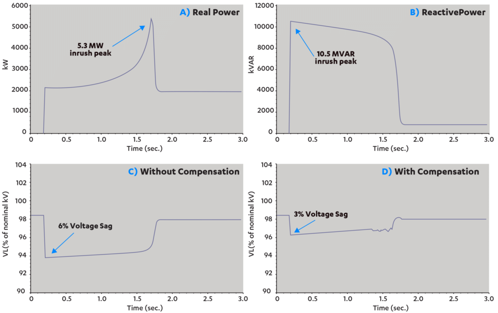
At start and during the acceleration, motors draw real and reactive power at levels which are many times higher than those at normal operating speed. This is referred to as the “in rush power” which, as seen in Figure 1-A) and 1-B), can easily reach as much as 10X the reactive and 3X the real power during normal operating conditions.
If not mitigated, the inrush power from large motors can cause the voltage to sag at the PCC (point of common coupling), resulting in operational problems such as an insufficient starting torque, heating of the motor windings and, often, violating the Utility PCC requirements.
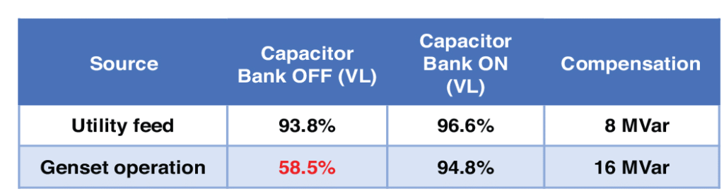
This is particularly problematic in networks with low short circuit current capability. Examples of such cases are sites connected at the end of utility distribution lines, or sites operating under local diesel generator power. In these scenarios, the voltage level and waveform are more sensitive to current levels and transients and, as shown in figure 2, the power inrush from the start of large motors can cause deep line voltage sags if not compensated for. In such cases, transformers and generators have insufficient current capacity for starting large inductive motors.
Capacitor Bank design
The design of the bank is critical to maintain voltage stability during motor start and power factor near unity during normal operation. A bank of minimum 2 and preferably 3 or 4 stages should be considered, with small and large stages sized to provide the necessary voltage control during ‘motor ramp-up’ and reactive power to maintain power factor requirements during normal operation at the PCC.
To avoid voltage sags, the system controls should be designed to connect the bank stages in synchronization with the start and ramp-up of the motors. Conversely, to avoid over voltage conditions, the controls must turn off the stages as the unit accelerates to nominal speed.
Comparison between VFD, RVSS and SynchroMVAR Capacitor Banks
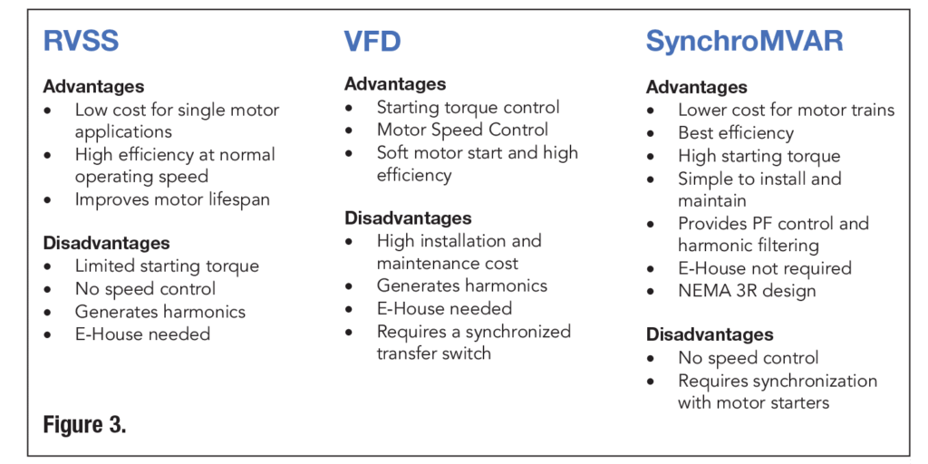
Opting between a VFD, RVSS or a capacitor bank, the system engineer should consider the advantages and disadvantages of each solution for the application. For example, an RVSS is a simple and inexpensive solution to deploy in a single motor application, but the limited starting torque could cause serious operational problems. Figure 3 provides a summary of the key advantages and disadvantages for each solution. Unless speed control is required as part of the normal process, SynchroMVAR proves to be an effective solution.
Cost Savings in Pumping Stations and Gas Compression Facilities
Perhaps the most compelling advantage of SynchroMVAR is the initial and on-going life cycle costs.
An RVSS is a simple and cost-effective solution for starting a single motor in an indoor environment. However, for a multi-motor application such as a large water or oil pumping stations, a separate RVSS would be required for each individual motor, which increases costs and footprint.
Large VFDs, on the other hand, are complex and expensive devices. Due to cost, the general practice in parallel motor applications is to use only one VFD in conjunction with a bypass and synchronized transfer switching system. This system is designed to connect the VFD sequentially with each motor during its starting sequence.
Unlike the RVSS or VFD, the SynchroMVAR capacitor bank connects in parallel with the motors. As such, one single bank supports the voltage during the start of every individual motor connected on the same power feed, and subsequently, provides the needed reactive current for power factor correction of the entire power feed.
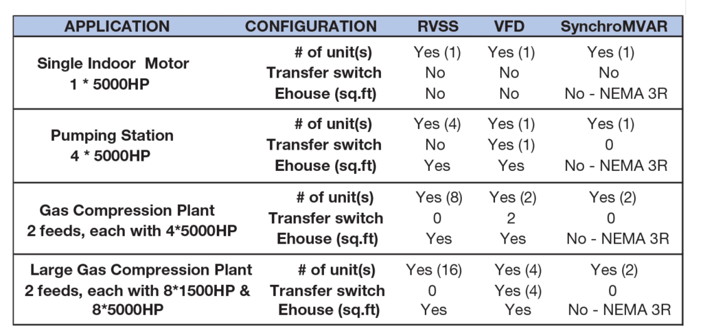
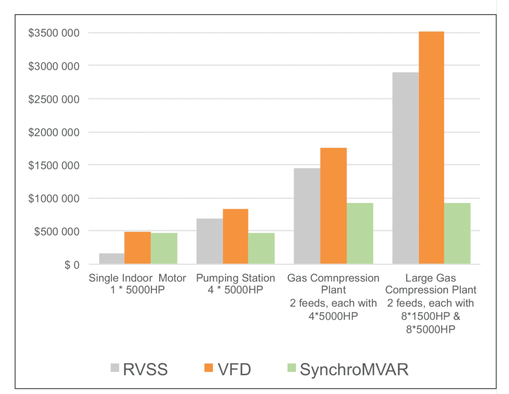
Figure 4A shows the configurations with these solutions are used to support the start of motor(s) in 4 typical applications, from an individual indoor motor in an industrial facility, to water and gas pumping stations, and finally medium and large gas compression plants.
Figure 4B shows the cost comparison. Except for the individual motor case where a single RVSS could be used to support the motor start, the SynchroMVAR proves to be the lowest cost solution in all other scenarios, and in fact significantly less expensive for the larger applications requiring multiple motors.
In addition, the SynchroMVAR supports the on-going need for reactive energy support and power factor correction, which eliminates the penalty from the Utility company, or otherwise requires the addition capacitor banks in the RVSS and VFD scenario.
Advantages Of SynchroMVAR Point-On-Wave Technology For Capacitor Switching
SynchroMVAR Point-On-Wave (POW) technology provides transient-free switching of capacitors. This limits the current and voltage transients which are generally produced with non-synchronous switching of capacitors. By eliminating these transients, the life of the switching devices and capacitors is prolonged significantly.
Alternative technologies such as Zero-Voltage Switching (ZVS) and Resistor Pre-Insertion (RPI) are also used for transient-free or reduced transient switching performance. Figure 5 below compares the advantages and disadvantages of these alternatives.
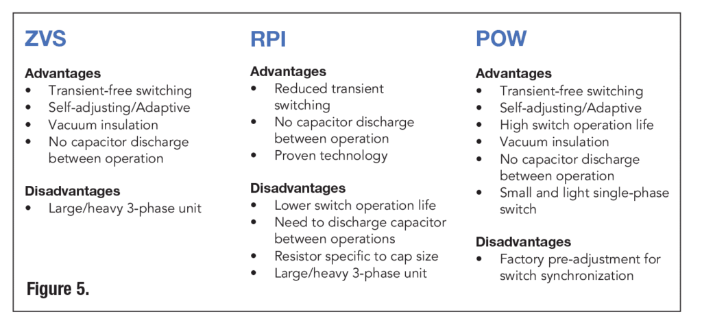
As can be seen, Point-On-Wave technology provides the most advantages. Specifically, POW eliminates the need to discharge the capacitors between cycles, a process which can take minutes to avoid degrading the life of the capacitors unnecessarily. It also uses single pole vacuum switches, which are lightweight and inexpensive, and unlike the large 3-phase switches for ZVS and RPI, easily replaced on site.
Summary
Starting large motors connected directly on-line represents a significant power challenge due to the large inrush current at start-up. SynchroMVAR Point-On-Wave switching capacitor banks are a low cost, effective alternative to VFDs, RVSSs, or alternative capacitor banks using zero-crossing or resistor pre-insertion switching.